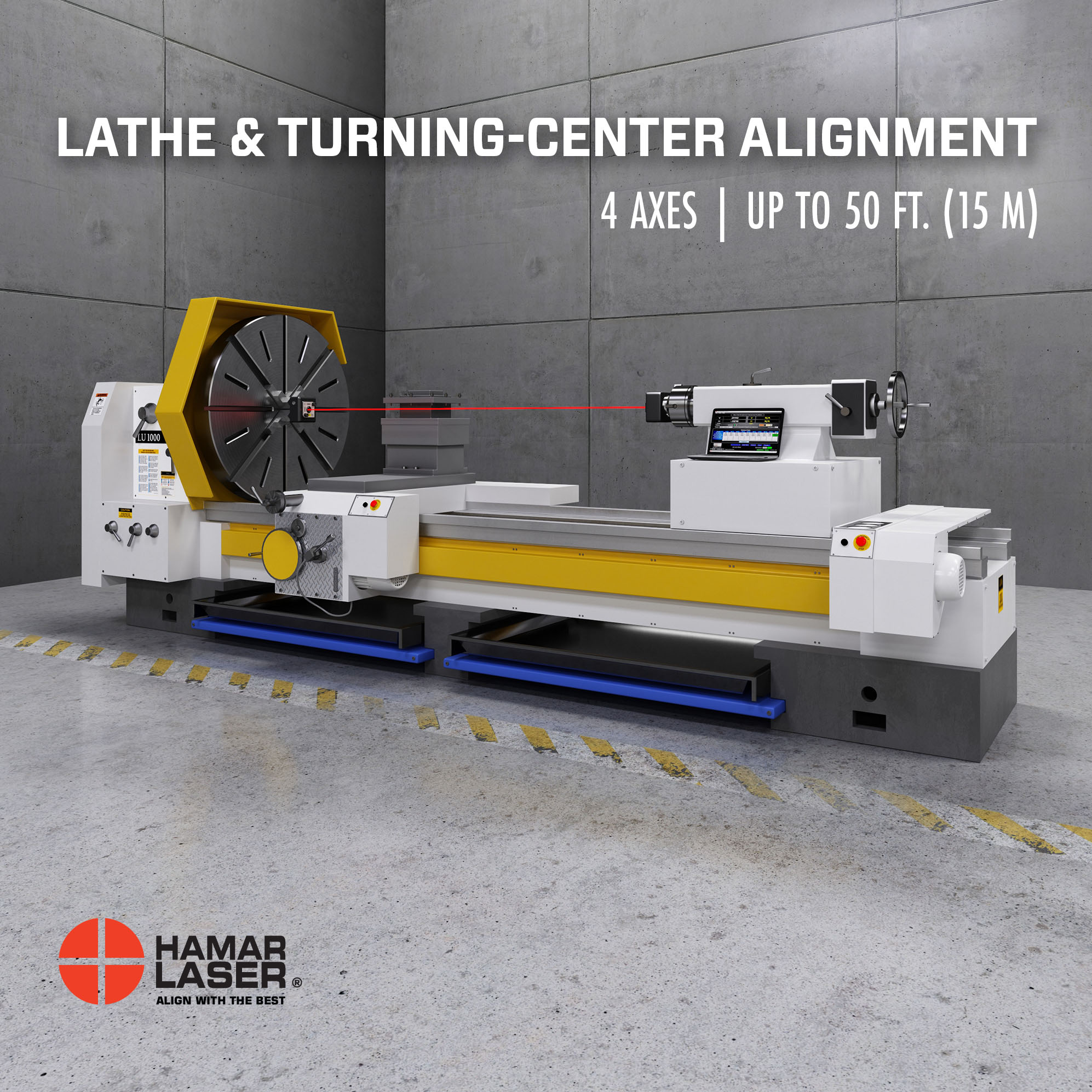
Have you ever thought about using a laser to align a lathe?
Traditional lathe and turning-center alignment often depends on dial indicators, alignment bars, levels and repeated mechanical setups. Those methods can work well, but they can also become time-consuming, particularly when several machine geometries must be checked.
Hamar Laser’s L-703S 4-Axis Spindle Alignment Laser System was designed to simplify the process.
With a resolution of .00001 in., the L-703S allows technicians to evaluate multiple lathe and turning-center alignment conditions while receiving measurement updates in real time.
Depending on the application, alignment can be completed up to 70% faster than conventional methods.
Check More Than Spindle Centerline
Lathe alignment involves more than positioning two centers relative to each other.
Several machine geometries can influence part accuracy, including the relationship between the headstock spindle, tailstock, machine guideways and steady rests.
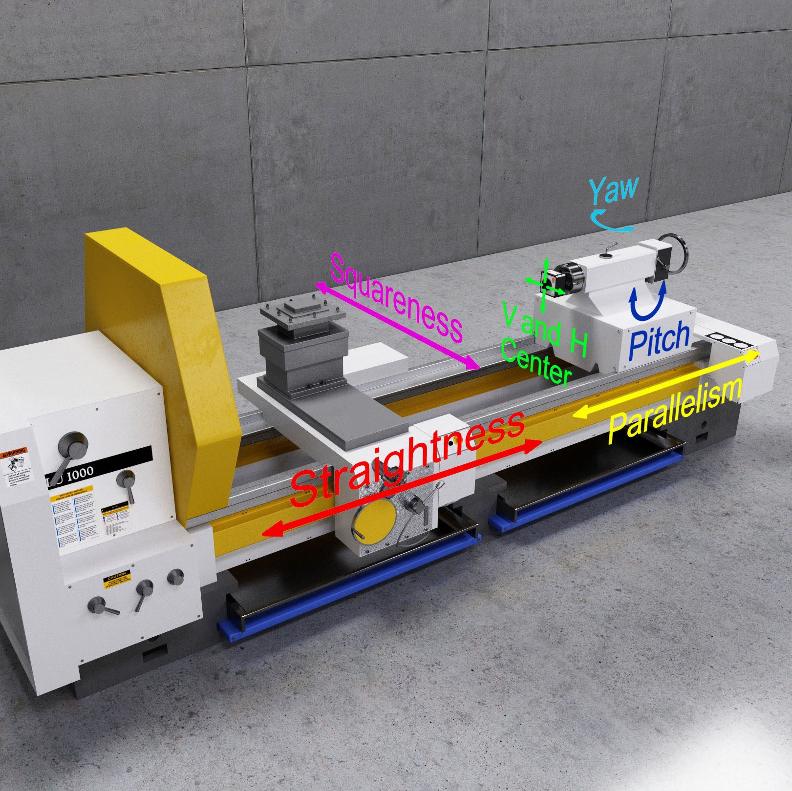
The L-703S can be used to check:
- Headstock-to-tailstock spindle alignment
- Headstock parallelism
- Guideway straightness
- Steady-rest alignment
- Spindle centerline position
- Angular alignment
These measurements can be performed in four axes using Hamar Laser’s T-1296 5-Axis Multi-Purpose Targets.
Measure Angular and Centerline Errors
A spindle can appear aligned at one point while still having angular error over distance.
Likewise, two axes may be parallel but offset from each other.
That is why measuring both angular and positional relationships is important.
The L-703S allows technicians to evaluate alignment in multiple axes instead of relying on a single indicator reading or a limited mechanical reference.
This gives a clearer picture of the actual machine geometry.
Real-Time Alignment Data
One of the biggest advantages of electronic laser alignment is the ability to see changes immediately while making adjustments.
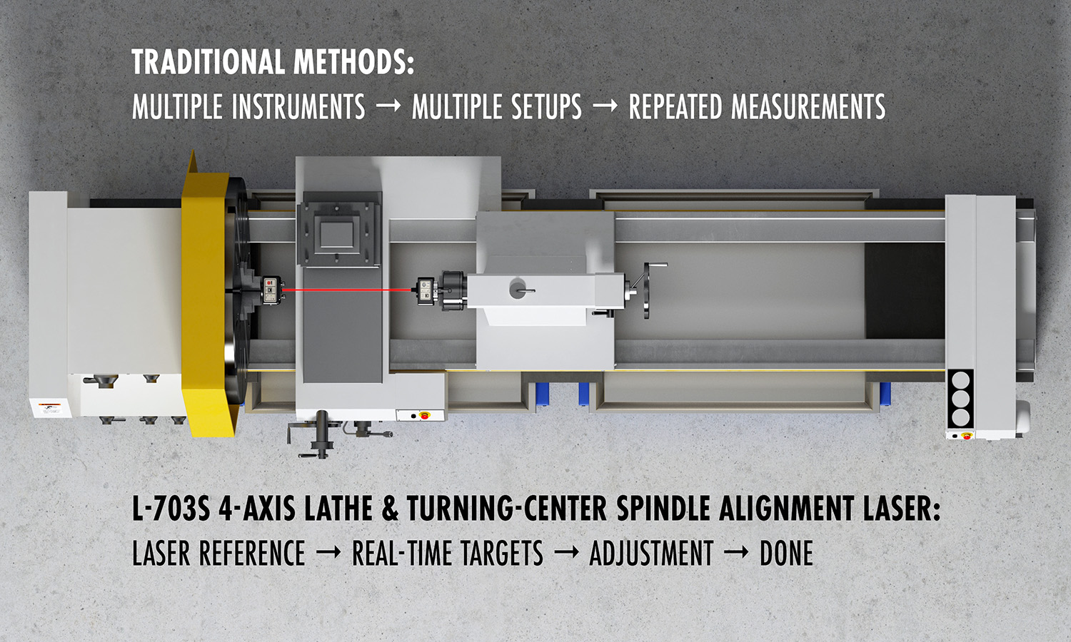
Target readings update in real time, allowing the technician to observe how the machine responds as components are moved.
Instead of:
Measure.
Stop.
Adjust.
Reset equipment.
Measure again.
The alignment becomes a more continuous process.
That can be especially useful when adjusting headstocks, tailstocks, guideways or steady rests where small mechanical movements can create measurable changes.
Large Lathes Are No Problem
Machine size can make conventional alignment significantly more difficult.
Long alignment bars can sag. Mechanical references become cumbersome. Small angular errors can also produce substantial offset errors over distance.
The L-703S has a measurement range of up to 50 ft. (15 m), making it suitable for everything from smaller machine tools to very large lathes and turning centers.
The laser establishes a long reference axis that allows measurements to be compared throughout the machine without physically spanning the entire distance with a mechanical tool.
Guided Alignment with Lathe10 Software
Measurement hardware is only part of the process.
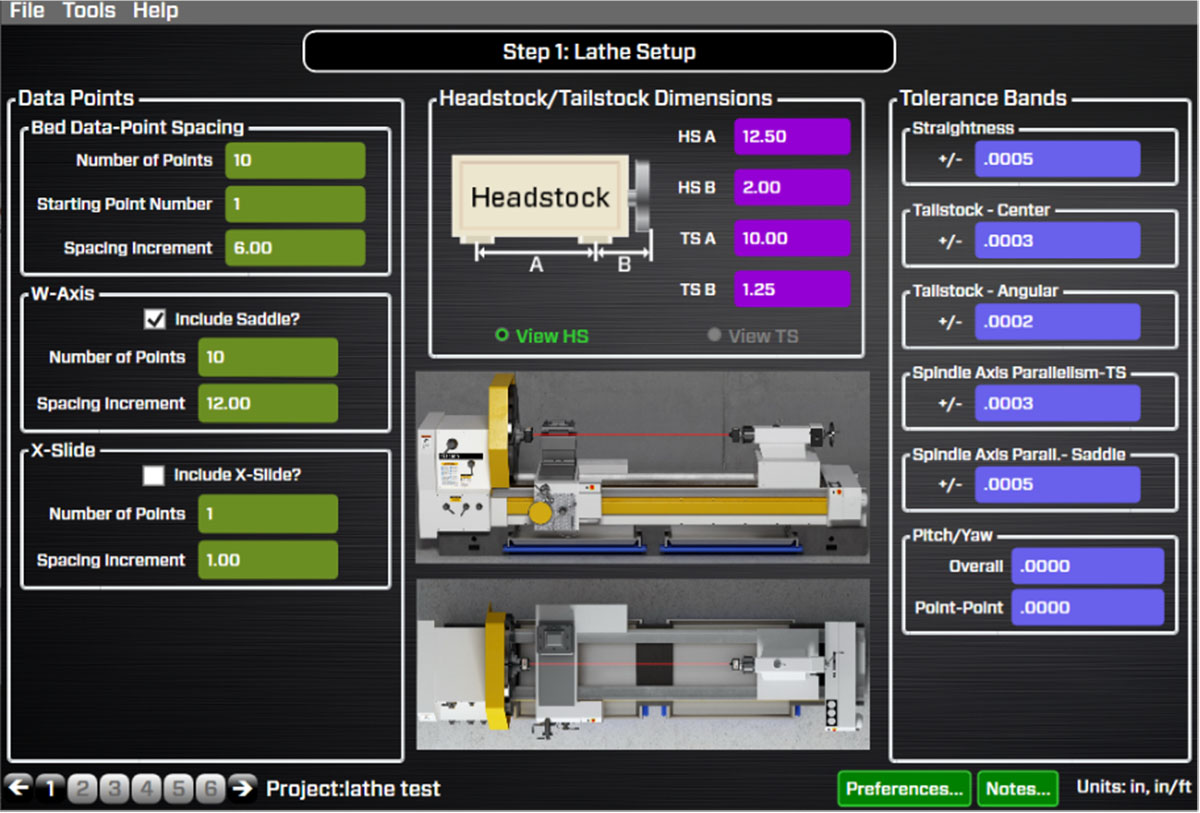
Hamar Laser’s Lathe10 Software provides a Windows-based interface that guides the user through the alignment using an easy six-step process.
The software helps organize the measurements, display alignment errors and guide the technician through the procedure.
This combination of laser hardware, electronic targets and alignment software reduces the amount of interpretation required during the job.
Faster Alignment Without Sacrificing Measurement Detail
The goal of the L-703S is not simply to replace a dial indicator with a laser.
It is to reduce the number of setups needed to understand the geometry of the complete machine.
When spindle alignment, parallelism, straightness and related measurements can be evaluated from a common reference, technicians can spend less time setting up instruments and more time correcting the machine.
That can shorten machine downtime while providing more complete information about the underlying geometry.
